DUCT DESIGN
The function of a duct design system is to transmit air from the air handling apparatus to the space to be conditioned.
It act has a transporting system from AHU TO CONDITIONED SPACE.
Well, the duct is a very important parameter in an air conditioning system, which act as a supplying agent which transmitted the treasury cold conditioned current suitable for the human being.
The duct is the medium through which desired cold or hot conditioned air is been supplied.
Well, the duct is used in the larger space where the cooling box or air conditioner system is organised at the particular junction and been connected to different space where conditioned air is been supplied via a system called duct.
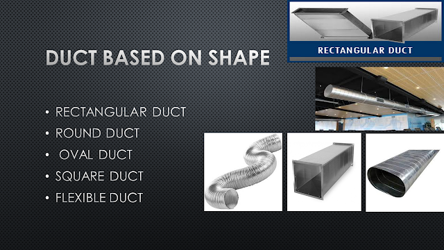
DUCT BASED ON SHAPE
Duct are been used depending on the various requirement and due to this, there are various shapes of duct available in the market.
We will surely dive deep in this topic but before that, we must go forward with the thing we need to understand for our betterment.
But we will have a shallow overlook on the shapes of the duct so we will be less curious about it.
Well as you can see that there are five duct shapes which is been mentioned in this article but there are most found duct shape in the market.
Basically square, round, rectangular oval, etc are the rigid ducts which are found everywhere where there is a presence of the cooling environment.
This duct are been chosen depending on various calculation that we are going to have a glimpse today.
But round and oval shape duct are generally used where there is no space issue over the false ceiling.
Well as you know, generally the ducts are been hidden from us with the help of false ceiling it might be in big shops, malls airports etc
The round and oval duct are used because it has less friction loss while flowing or moving the cool air.
But if space is considered then we get inclined towards rectangular duct but nowadays capsule type of duct which is a combination of round and rectangular are been used as it is less space-consuming and less friction too but increase the fiscal stance.
If we look at flexible duct, this is the duct which has a flexible wire covered with silver-coated cover generally used where the rigid duct is less possible to connect.
Flexible duct as the name is a flexible product which can be turned and twisted to supply conditioned air.
It is generally used where changes occur in the site and the rigid duct is less possible to use in a very small and critical space but if twisted more there are higher chances of losses so recommended less.
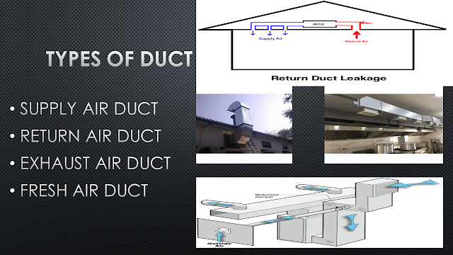
TYPES OF DUCT
Basically, there are 4 types which are common in the industry of HVAC
Well, let's move where are been this duct used for ….?
The supply air duct is used where the cold current of conditioned air is been supplied…
The return air duct is the duct which extracts or take away the used conditioned air in the conditioned space, this used air is been sucked by the air conditioner system by creating negative suction energy with high-speed motors.
The exhaust air duct is generally used in the place where the air in the surrounding area non-inhalable and hence it has to be removed and make a provision for fresh air, at which such duct are been used.
The fresh air duct is a duct which makes the provision for fresh air in an area where the non-inhalable gas has been removed and fresh air take that space …
DUCT MATERIAL
Well, duct plays a very important role in transmitting the conditioned air to required space, it is also necessary to look after the material which is been used in the ductwork so that it can withstand the high pressure and various temperature of the conditioned and non-conditioned air.
So let's have a look at the types of material used in duct making.
Galvanised steel
Galvanised mild steel is the standard and most common material used in fabricating ductwork because the zinc coating of this metal prevents rusting and avoids the cost of painting.
Aluminium (Al)
Aluminium ductwork is lightweight and quick to install. Also, custom or special shapes of ducts can be easily fabricated in the shop or on-site.
Flexible ducting
Flexible ducts (also known as flex) are typically made of flexible plastic over a metal wire coil to shape a tube.
Flexible duct is very convenient for attaching supply air outlets to the rigid ductwork.
It is commonly attached with long zip ties or metal band claps. However, the pressure loss is higher than for most other types of ducts.
Fabric ducting
The term fabric duct air dispersion system would be the more definitive name. However, as it often replaces hard ductwork, it is easy to perceive it simply as a duct.
Usually made of polyester material, fabric ducts can provide a more even distribution and blending of the conditioned air in a given space than a conventional duct system.
What is the fundamental requirement of DUCT
Energy efficiency: Faulty ductwork can result in air loss. This can increase your energy bills as your AC works to accommodate for the loss.
Better comfort: uneven cooling is a common sign of faulty ductwork, so having good ductwork helps ensure better comfort inside your home.
Good air quality: just as air can escape from your ductwork, outdoor air can get in through the same holes and cracks. This means particles and even exhaust fumes from other large household appliances can enter your airflow and decrease the quality of your indoor air.
So after having the basic knowledge of ducting we are eligible to move ahead with designing of the duct.
There is a various aspect which needs to be taken care of while designing the duct for any project.
A good designer always gives a good product to the society with the most efficient knowledge obtained in the field of HVAC.
A good designer should take care of Energy efficiency, Better comfort and Good air quality.
So taking into it into consideration lets move with the designing procedure.
DUCT DESIGN
Aspect ratio: this is the ratio of the long side of the duct to the shorter side of the duct.
As the aspect ratio increases more metal surface is required for the duct of the same cross-section.
So after reading the above line, we will be not clear with it, obviously, it needs an explanation.
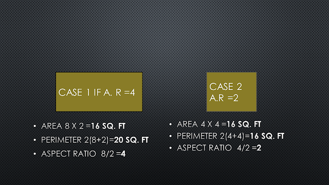
So don’t worry we will have a clear picture by having an example from the above slide.
As we can see that there are two cases
In which cross-section of both cases are the same
But perimeter of case 1 is more than that of case 2…
In case 1, the Aspect ratio is 4
In case 2, the Aspect ratio is 2
So as the aspect ratio increases more the metal surface of the duct required for the same cross-section.
Hope we are clear with it.
Hence it is necessary that aspect ration should be less than 4.
As the aspect ratio decreases, less sheet metal surface in contact with air results in a decrease of the friction and running cost of the project.
At the time of designing, we should try to make the duct shape similar to the square.
Now, let us move on different types of method used in duct design.
- EQUAL FRICTION METHOD OR CONSTANT PRESSURE METHOD
- VELOCITY REDUCTION METHOD
- CONSTANT VELOCITY METHOD
- STATIC REGAIN METHOD
Before understanding this method it is necessary to understand the basic formula of the continuity equation.
So CONTINUITY EQUATION
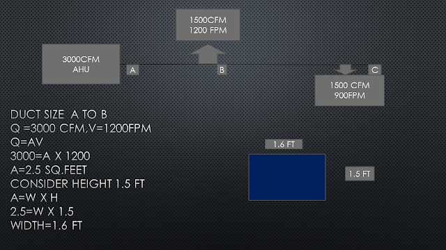
Q=AV
Where Q = flow rate of air in cubic feet per minute CFM
A= cross-sectional area of the duct
V= velocity of air in feet per minute FPM.
So let have an example to clear all the doubt which may be arriving in our minds.
Well from the example we could find that, AHU consist of 3000 CFM which is the quantity of air, and we assume velocity to be 1200 FPM.
So using the equation we get the area of the duct ….
So after understanding having a clear idea we will move forward with a different method.
EQUAL FRICTION METHOD OR CONSTANT PRESSURE METHOD
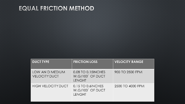
With this method, the same value of friction loss rate per length of the duct is used to size each section of the duct.
The friction loss rate is chosen to result in an economical balance between duct cost and energy cost.
A higher friction loss results in smaller ducts but higher fan operating cost.
This method is almost universally used for supply, return, fresh and exhaust duct for low and medium pressure up to 4`` of w,g.
Well after coming across the above line you might have a basic introduction of what the equal friction method deals with.
Basically in this method, we have to keep the friction in duct while the air moves in it to be constant.
So let's take an example which surely removes all the confusion!!!!!!!!!
So let's take an example with a system of 4000 CFM capacity as shown in the figure., which also have some basic details of application which is home, friction rate which is 0.08 inches of w.g /100`` and height of duct to be 14 inches according to available space over the false ceiling.
let's take an example at section A-B
Flow rate is 4000CFM
Friction loss is 0.08`` of W.G
So basically there are two ways we can find out the duct area
Friction chart
so it is a graphical chart through which we get important parameter necessary for duct size.
It is basically air quantity in CFM which is on vertical axis vs friction loss which is in horizontal axis chart which is used to find the diameter area of the duct from the chart having friction known and air quantity known
So let's find out diameter area for air quantity 4000 CFM and friction loss 0.08`` of W.G
So we 24`` of diameter
So as we know diameter is 24`` and height is 14`` of duct assumed.
So from the chart on horizontal line find 14`` and in that column find 24`` you will find from the chart 23.9``and 24.5 ``choose bigger no. i.e 24.5 and move towards the left side in a row you will find 38`` which is your width.
Hence 14`` x 38`` is the area for section A -B and so on for other section….
So that’s all about the manual or frictional chart method so let move forward with software method.
Duct sizer software.
Just put the value of air quantity 4000 CFM, Head or friction loss 0.08`` of w.g, assumed duct height 14`` you will get above results.
Carry on with other section and you will get the following data.
ADVANTAGES
AUTOMATICALLY REDUCES AIR VELOCITY IN THE DIRECTION OF AIRFLOW FOR SUPPLY AIR.
BALANCED DESIGNING WITH RESPECT TO INITIAL AND RUNNING COST
QUICK AND EASY METHOD
IF THE DUCT LAYOUT IS SYMMETRICAL NO DAMPERS REQ. FOR BALANCING.
DISADVANTAGES
NOT SUITABLE FOR LONG RUN DUCT( DUCT MORE THAN 30` IN SINGLE SECTION)
VCD ( air controlling device) REQUIRE IF IT IS NOT SYMMETRICAL.
VELOCITY REDUCTION METHOD
The size of the main duct is established by selecting a velocity from the recommended range, as done in the equal friction method.
Therefore for every duct section taken out, reduced velocity is selected based on previous experience with velocity and CFM, and hence duct size are determined.
This method is though simple, but not used in actual practice because this does not take into account relative pressure losses in various branches.
CONSTANT VELOCITY METHOD
In this method, the velocity throughout the duct system is kept constant.
Initial selected velocity is very low, compared to other duct design methods.
This is generally for greater comfort especially for high-class projects where comfort is the priority.
The initial selected velocity is low, as friction is less and the noise level is less.
STATIC REGAIN METHOD
The static regain method of sizing the duct is most often used for high-velocity systems with long ducts runs, especially in a large installation.
In this method, the initial velocity of the main duct leaving the fan is selected in the range of 2500-4000 FPM.
After the initial velocity is selected, the velocity in each successive section of the duct in the main run is reduced, so that the resulting pressure gain is enough to overcome the friction losses in the duct section.
As a result, the static pressure is the same at each junction balanced and simplified.
So before moving on we need to understand what the static pressure is actually??
So let's take an example of the air-filled balloon the air pressure which is exerting on the surface of the balloon is called as static pressure and the flow with which the air flows inside the balloon is called as velocity pressure.
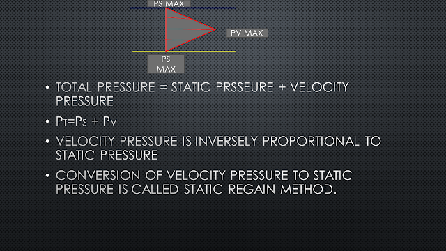
Now as per drawing above let's take an example of a duct in which the air is flowing, so the pressure exerted by the air on the inner surface of the duct is called static pressure.
Similarly, the air flowing with some velocity is called velocity pressure.
And the addition of both the pressure is called as Total Pressure.
If you noticed the velocity pressure in the duct is maximum at the centre of the duct whereas at the surface of the duct it is almost zero.
And the static pressure at the centre of the duct is zero while at the surface it is maximum.
Well static regain means converting the velocity pressure to static is called a static regain method or gaining pressure is called a static regain.
Well, this method concentrates on increment on static pressure over frictional pressure losses and overcoming it.
MATHEMATICALLY,
STATIC PRESSURE = R X [(V1/4000)² - (V2/4000)²]
V1 = VELOCITY AT PREVIOUS SECTION OF THE DUCT
V2 = VELOCITY AT CURRENT SECTION OF THE DUCT
R = RECOVERY FACTOR, DEPENDS ON THE SHAPE OF THE DUCT FITTING THAT CHANGE VELOCITY (0.7 TO 0.9)
STATIC PRESSURE = R X [(V1/4000)² - (V2/4000)²]
V1 = VELOCITY AT PREVIOUS SECTION OF THE DUCT
V2 = VELOCITY AT CURRENT SECTION OF THE DUCT
R = RECOVERY FACTOR, DEPENDS ON THE SHAPE OF THE DUCT FITTING THAT CHANGE VELOCITY (0.7 TO 0.9)
So let's take some example for method understanding.
So let take section A-B
Taking velocity which is higher 4000 FPM, duct length 50 ft,12000 CFM
So by using duct sizer we will get other details
Well we get the following details of friction loss or head loss in w.g per 100`` is 0.832 but duct length of section A-B is 50ft therefore friction per duct length will be 0.832 x 50/100 we will get 0.416 for 50ft of the duct.
In the first section, we do not consider static pressure because as per STATIC PRESSURE = R X [(V1/4000)² - (V2/4000)²] it requires two different velocities.
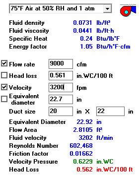
Now let's take the second section from B-C having 9000 CFM velocity assuming 3200 for 40ft length so lets put all data into duct sizer.
Now we have to find using these details whether the static pressure is greater than the friction pressure per duct length.
PRESSURE = R X [(V1/4000)² - (V2/4000)²]
V1 = VELOCITY AT PREVIOUS SECTION OF THE DUCT =4000FPM
V2 = VELOCITY AT CURRENT SECTION OF THE DUCT=3200FPM
R =0.9
V2 = VELOCITY AT CURRENT SECTION OF THE DUCT=3200FPM
R =0.9
As you can see that static pressure 0.324 is greater than friction pressure per duct length 0.224 hence this velocity is selected.
If the static pressure will be less friction pressure per duct length we have to choose different velocity…
Similarly, we have to carry on this last until and unless we get all value of duct size…
ADVANTAGES
SUITABLE FOR LONG AS WELL AS SHORT RUN
NO BALANCING REQUIRED
ACCURATE METHOD
DISADVANTAGE
TIME-CONSUMING METHOD
This is the four types of methods in duct design which are used to find out duct size in which equal friction method is mostly used for residential whereas static regains methods are used for industrial .this are the most common method which is used to find the duct size. hope we have a clear idea about duct sizing and all ducting related topics.









0 Comments